
handleiding 5600 SXT Fleck
handleiding 5600 SXT Fleck
Handleiding 5600 SXT Fleck en technische informatie in alle talen klik hier pentair
Download de pdf handleiding 5600 SXT Fleck
handleiding 5600 SXT Fleck
handleiding 5600 SXT Fleck
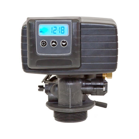
Service indicator:
– Valve in service: lighted icon
– Night regeneration: flashing icon
Information indicator, viewed in Diagnostic &
Error modes
Indicator in programmation mode
Flow indicator
Multiplication indicator: numbers shown have
to be multiplied by 1000
Time clock regeneration
The number of days between each regeneration cycle is preset. Once reached, regeneration is
triggered at the programmed time.
7 day time clock regeneration
The regeneration is based on the days of the week: Monday, Tuesday,… Sunday. The electronics
will trigger a regeneration based on the defined days of the week at the set time.
Metered regeneration
The valve calculates the amount of water it can soften between 2 regenerations based on the
exchange capacity (m3
°tH) and inlet water hardness that are preset.
Immediate or meter delayed regeneration
As softened water is used, the remaining volume display will decrease until reaching its reserve
capacity (meter delayed regeneration) or until zero (immediate metered regeneration). When
this happens, regeneration is automatically triggered either straight away or at a preset time.
Service
Service display
In operation, in volumetric mode, the time of the day and the volume remaining will alternatively
be displayed. In time clock mode, the display alternates between the time of day and the
remaining days. In Twin mode, the time of the day, volume remaining and tank in service displays
will alternatively be displayed.
Time of day Remaining volume: 2300 litres Remaining days before Tank in service,
next regeneration Twin mode : 9000/9100/9500
Time of day setting
Press and hold the buttons or until the icon and the letters « TD » appear on the
display.
Use and buttons to adjust, then press the button to return in service.
Regeneration
regeneration displays
During the regeneration cycle, the valve will show the cycle number name it is advancing to
(flashing display) or has reached as well as the time remaining in that cycle (fixed display). Once
all the regeneration cycle steps have been completed the valve will return to the service position.
The valve is in backwash position; the display indicates the
remaining time.
1 – VALVE OPERATION
E
N
G
L
I
S
H
Start a manual regeneration
There are 2 options to initiate a manual regeneration:
A) Press and release the button .
The icon will start flashing, to cancel the regeneration request press button, the icon will
stop flashing.
The regeneration will start at the set hour.
B) Press and maintain for 5 seconds the button, the regeneration will start immediately.
Advance to the next regeneration cycle
To advance to the next regeneration cycle, press the button. This will have no effect if the
valve is already advancing to the next cycle.
PROGRAMMING
Caution: The programming has to be done only by the installer for the setting of the valve
parameters. The modification of one of these parameters could prevent the good functioning of
the device.
To enter the programming mode, the valve has to be in service. While in program mode, the valve
will continue to operate normally monitoring all information. The programming is stored in
permanent memory with or without line or battery backup power.
To enter the programming mode, press simultaneously and for 5 seconds.
Press on the button in order to jump to the next stage. Use the and buttons in order to
modify the displayed values.
Note: You must pass through all the programming steps and come back in service position to
save the modifications that have been done during the programming mode.
* 1=Monday – 2=Tuesday – 3=Wednesday – 4=Thursday – 5=Friday – 6=Saturday – 7=Sunday
VALVE OPERATION DURING A POWER FAILURE
During a power failure, all the data will be saved and restored once the line power is restored.
The data can be saved for many years with no loss. The electronics will be inoperative, the
display shut down and all regeneration will be delayed.
The electronics will restore all the information to the time where the power failure occurred. The
valve does not record the amount of water used during a power cut.
During the power supply restoration, the hour display will flash to indicate that a power failure
occurred.
Set the clock on 12:01, and exit time of day programmation
mode by pressing . Then press simultaneously on the
and buttons for 5 seconds.
1. Display unit (DF)
– Gallon [GAL]
– Liter [Ltr]
2. Valve type (VT)
– Down flow, 1 backwash (standard) [dF1b]
– Down flow, 2 backwashes [dF2b]
– Filter, except 5000 [Fltr]
– Up flow, brine draw first [UFbd]
– 5000 Filter [UFtr]
– Other [Othr]
3. Regeneration type (CT)
– Time clock [tc]
– Weekly time clock [ d A Y ]
– Metered delayed [Fd]
– Metered immediate [FI]
4. Valve type (NT)
Valves 9000-9100-9500
Tank in service
i.e.: tank 1 in service
5. System capacity
Only viewed in metered version
– Metrical format m3
x°tH, i.e.: 200 x1000lx°tH
meaning 200 m3
x°tH
6. Inlet water hardness (H)
Only viewed in metered version
– Metrical format, French degrees
7. Reserve type (RS)
7.1 Reserve with a fixed volume (RC)
i.e.: 1200 liters
7.2 Safety factor in % (SF)
i.e. : 15% capacity of reserve
8. Regeneration day override (DO)
i.e. : regeneration every 7 days
9. Regeneration time (RT)
i.e.: Regeneration at 2:00 AM
10. Regeneration cycle time setting
10.1 Backwash (BW)
i.e.: 10 min
10.2 Brine draw & slow rinse (BD)
i.e.: 60 min
10.3 Rapid rinse (RR)
i.e.: 10 min
10.4 Brine tank refill (BF)
i.e.: 12 min
11. Define the regeneration days of week
Viewed in time clock week mode
11.1 – Regeneration on Monday
11.2 – No regeneration on Tuesday
11.3 – No regeneration on Wednesday
11.4 – No regeneration on Thursday
11.5 – Regeneration on Friday
11.6 – No regeneration on Saturday
11.7 – Regeneration on Sunday
11.8 – Day of the week to be indexed
i.e.: Thursday
12. Meter type
– 3/4″ turbine [ t 0 . 7 ]
– 3/4″ wheel [ P 0 . 7 ]
– 1″ turbine [ t 1 . 0 ]
– 1″ wheel [ P 1 . 0 ]
– 1″ 1/2 turbine [ t 1 . 5 ]
– 1″ 1/2 wheel [ P 1 . 5 ]
– 2″ wheel [ P 2 . 0 ]
– Other meters [GEn]
Meters ‘not’Fleck®
Viewed in Meter mode [ GEn]
i.e.: 0.5 impulsions / liter [0.5]
1. Press once the button
to go from one display
mode to another.
2. Set parameters values by
using the and
buttons.
3. Depending on the
programmation, some
displays will not appear
and some will not be
variable.
Return in service mode
H
ERROR DISPLAY (ER)
The codes only appear in service mode
When an error occurs, the lighting of the display will flash as well as the exclamation point, the
letters ER and the error code will be displayed.
There are 4 possible error codes:
RESET
When this operation is done, it will be necessary to check all stages of the programming.
All parameters will be automatically set to default settings. Unplug the unit, press and maintain
the button while powering up the valve again, the valve will display :
2.2
ERROR ERROR CAUSE CORRECTION
CODE TYPE
The valve drive takes more than
6 minutes to go to the next
regeneration cycle
The valve performed
an unforeseen cycle
System has not regenerated
for more than 99 days, or 7 days
in 7 day time clock mode
Circuit board memory failure
0
1
2
3
Cam sensor error
Cycle position
Regeneration
Memory
Unplug the unit and examine the power head.
Check that:
– Everything is correctly connected to the circuit
board.
– The motor and gear are in good condition and
correctly assembled.
– Piston moves freely in the valve body.
Replace/re-assemble the different parts if
necessary. Connect back the unit and observe
its behavior. The valve should move to the next
cycle and stop there. If the error reappears,
unplug the valve and contact the technical
support.
Unplug the unit and examine the power head.
Check that everything is correctly connected to
the circuit board.
Enter the programming mode and verify that
valve and system types are properly set in the
system.
Initiate a manual regeneration and verify the
operation.
If the error reappears, unplug the valve and
contact the technical support.
Initiate a manual regeneration to remove
the error code. If it is a volumetric valve,
verify that the consumption of water is correctly
registered on the circuit board display. If there is
no counting, check the meter cable connection
and the meter functioning.
Enter the programming mode and verify that the
system is configured correctly; that the settings
match to the configuration of the valve, and that
the system capacity, and the day override are
set correctly, and that meter is correctly
identified.
Reset the programming and reconfigure the
system. After the programming, initiate a
manual regeneration. If the problem persists,
contact the technical support.
Press simultaneously the buttons and for 5 seconds. Use the buttons and to go
from a display to the next one.
Instantaneous flow rate (FR)
The unit that should be read is the one set in display unit.
Peak Flow rate registered (PF)
Number of hours since the last regeneration (HR)
Volume used since the last regeneration (VU)
Reserve capacity (RC)
Software version (SV)